Microcontroller And Electronics
Contents |
Re-programming the on-board Arduino Compatible
The veeOP has an on-board arduino compatible, allowing you to customize it to the fullest extent.
The tool included with the downloadable distros here is the InoTool, a command-line Arduino tool. To get into the details, check out their installation guide, and their quick-start guide. But, we'll go over the details here, too.
In the distros provided here in the home directory for the "pi" user, you'll find a directory named 'arduino-vop' which already has an editable version of the code that's already on the microcontroller that you can use to get started!
Installing the necessary tools
If you're not using a veeOP customized distro, you might wish to install the tools from scratch. The examples given here are from PiDora (the Fedora distro for the pi), but, can be easily applied to most distros.
For example, where I say "yum install package_name" under a Debian-based distro you can use "apt-get install package_name".
Using Arduino Shields with your veeOP
The veeOP is designed to be able to extend it using Arduino Shields. There are shields for all kinds of applications
- GPSr (global position system recievers)
- GSM (cell phone service)
- LCD Displays
- Wireless (like the ZigBee / XBee)
- And much, much more.
Are you new to Arduino?
Don't sweat it! The Arduino is intended to be an approachable technology, and one that gives a new user a lot of power. And, you'll feel great interacting directly with microcontrollers. The best part is, you can use your veeOP to help you learn.
You can log onto the veeOP connected to your raspberry pi, but, you might want to download the Arduino IDE (integrated development environment) and get started on your workstation (your laptop or desktop computer). You can compile the veeOP code right there to do some initial testing and exploration.
Some resources you might be interested in:
- Getting Started With Arduino
- Arduino Software Download
- O'Reilly Arduino Development Landing Page
- The Arduino Cookbook
The I²C API
The I²C API on the microcontroller is a rather simple little set of commands that rides on I²C. For more information about I²C we direct you to Wikipedia.
The veeOP uses the Raspberry Pi as the I²C master, with the arduino-compatible being the slave, at address 4 (0x04) by default (this is configurable in the library.)
How Commands are transmitted
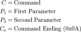
Commands are sent to the veeOP arduino-compatible with a 4-byte tuple. It looks like so:

Where each element is a single byte, representing:
-
 (command) is any (known) value other than 10 (0x0A, in hex.) and originally assigned all higher 10.
-
 &
&  are sometimes treated as individual integer values each, or together as a 16 bit integer, depending on context.
-
 Command ending allows the microcontroller know when a command is incomplete, or too many bytes are sent.
How responses are received
When the microcontroller recieves the proper 4 bytes for the command, it responds in turn with a response of 4 bytes.
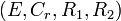
Where each element is a single byte, representing:
-
 errors of a value of 0 denotes an error-free response, any non-zero value is defined in a table below.
-
 is a redundant byte that represents from the sent command. This is used for error handling on the raspberry pi.
-
 &
&  are the resulting responses from the command. Treated as two bytes, or a 16-bit unsigned integer depending on the context of the command.
Commands
| Command Description | Value | |
|
Returns Int? | Example Command | Example Response | Example Description |
|---|---|---|---|---|---|---|---|
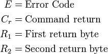
| Check Ignition State | 11 | - | - | Yes. | 
|
|
Response showing the ignition is on. |
Error Codes
| value |
Code Constant | Description |
|---|---|---|
| 1 | ERR_BUFFER_OVERFLOW | Too many bytes received before
|
| 2 | ERR_COMMAND_UNKNOWN | Command is unknown. |
| 3 | ERR_COMMAND_INCOMPLETE | Request for data from master received before sent.
|
Advanced Resources

Other resources that were valuable as the interface between the veeOP board and Raspberry Pi for programming the onboard arduino-compatible:
- Triggering microcontroller reset using Raspberry Pi's GPIO
- Another approach to programming an arduino compatible using a Raspberry Pi
- Fixing the DTR Pin
- Logic Level example schematics from eLinux
- eLinux's Serial Connection article
- An article about connecting serial communications to the Arduino from the Raspberry Pi