Difference between revisions of "Microcontroller And Electronics"
(→Re-programming the on-board Arduino Compatible) |
|||
| (7 intermediate revisions by one user not shown) | |||
| Line 7: | Line 7: | ||
In the distros provided here in the home directory for the "pi" user, you'll find a directory named 'arduino-vop' which already has an editable version of the code that's already on the microcontroller that you can use to get started! | In the distros provided here in the home directory for the "pi" user, you'll find a directory named 'arduino-vop' which already has an editable version of the code that's already on the microcontroller that you can use to get started! | ||
| + | [[Image:aon-jumper-web.png|thumb|225px|Location of the "always on" (A-ON) header/jumper on the veeOP. (Shown with jumper off)]] | ||
| − | === | + | === Hardware Steps === |
| − | + | One important step if you're going to re-program the microcontroller on the veeOP is to use a jumper on the "A-ON header" (short for "always on"). Because the veeOP controls power to the Raspberry Pi, when programming it -- you don't want the veeOP to turn off your Raspberry Pi. When a jumper is on this header, it makes it so that the Raspberry Pi is always in an on state. It's also imperative that you take the jumper off when you're ready to put the veeOP back in your vehicle, as it won't function the way it's intended! ...As you might imagine. | |
| − | + | Another option for programming the on-board arduino compatible microcontroller is to use the FTDI header on the board. This allows you to use an FTDI cable (which is basically a USB-to-RS232 adapter) to reprogram the microcontroller. Allowing you to program the micro without using the Raspberry Pi. However, since this also supplies the board with power, it's important that you do not have a micro USB cable attached, too. | |
| + | Your veeOP should come with jumpers provided. However, if you are to lose them, any standard jumper from a PC will also work. (Or you can wrap a wire around them, in a pinch.) | ||
| − | == | + | === Installing the necessary tools === |
| − | + | If you're not using a veeOP customized distro, you might wish to install the tools from scratch. The examples given here are from Raspbian, but, can be easily applied to most distros. | |
| − | + | First install Arduino and the requirements for inotools | |
| − | + | ||
| − | + | ||
| − | + | ||
| − | + | ||
| − | + | sudo apt-get install arduino | |
| + | sudo apt-get install python-setuptools | ||
| + | sudo apt-get install picocom | ||
| − | + | Then install ino with easy_setup | |
| − | + | sudo easy_install ino | |
| − | + | Add the pi user to the tty group | |
| − | + | sudo usermod -a -G tty pi | |
| − | + | ||
| − | + | ||
| − | + | ||
| − | + | And make a symlink to the tty that inotool / arduino likes... | |
| − | + | sudo ln -s /dev/ttyAMA0 /dev/ttyACM0 | |
| − | + | And make sure it's writable | |
| − | + | sudo chmod o+w /dev/ttyAMA0 | |
| − | + | == Download the code! == | |
| − | + | ||
| − | + | ||
| − | + | ||
| − | + | : ''Main Article:'' [[Downloads]] | |
| − | + | ||
| − | + | ||
If you're using one of the downloadable pre-customized distros, you can look in: | If you're using one of the downloadable pre-customized distros, you can look in: | ||
| Line 63: | Line 55: | ||
It's as simple as placing the vOP folder into your libraries folder in your Arduino's default install directory, to compile it. Check out the provided example sketch as it will guide you into extending the functionality. You can use the provided example sketch to keep the veeOP functionality intact, but! Use the microcontroller for other purposes, and it's extend it's functionality. | It's as simple as placing the vOP folder into your libraries folder in your Arduino's default install directory, to compile it. Check out the provided example sketch as it will guide you into extending the functionality. You can use the provided example sketch to keep the veeOP functionality intact, but! Use the microcontroller for other purposes, and it's extend it's functionality. | ||
| − | |||
| − | + | == Using Arduino Shields with your veeOP == | |
| − | + | The veeOP is designed to be able to extend it using Arduino Shields. There are shields for all kinds of applications | |
| − | + | * GPSr (global position system recievers) | |
| + | * GSM (cell phone service) | ||
| + | * LCD Displays | ||
| + | * Wireless (like the ZigBee / XBee) | ||
| + | * And much, much more. | ||
| − | : | + | [[Image:VeeOP_v003.png|thumb|350px|The veeOP schematics as of v0.300]] |
| − | + | ||
| − | + | ||
| − | + | ||
| − | + | ||
| − | + | ||
| − | + | ||
| − | + | ||
| − | + | == The Schematics == | |
| − | + | ||
| − | + | ||
| − | + | ||
| − | + | ||
| − | |||
| − | + | An extensible platform isn't exactly that without knowing how to really dig deep into the electronics. You can simply use the board "like an attached Arduino-compatible" -- or you can really get in and hack it how you want. | |
| − | + | Or! You can even build your own. We've included the schematic to show you that we really do care about the Open Source Hardware (OSHW) movement. | |
| − | + | == Are you new to Arduino? == | |
| − | + | Don't sweat it! [http://arduino.cc/ The Arduino] is intended to be an approachable technology, and one that gives a new user a lot of power. And, you'll feel great interacting directly with microcontrollers. The best part is, you can use your veeOP to help you learn. | |
| − | : | + | You can log onto the veeOP connected to your raspberry pi, but, you might want to [http://arduino.cc/en/Main/Software download the Arduino IDE] (integrated development environment) and get started on your workstation (your laptop or desktop computer). You can compile the veeOP code right there to do some initial testing and exploration. |
| − | + | ||
| − | + | ||
| − | + | ||
| − | + | ||
| − | + | ||
| − | + | ||
| − | + | ||
| − | + | Some resources you might be interested in: | |
| − | + | ||
| − | + | ||
| − | + | ||
| − | + | ||
| − | + | * [http://arduino.cc/en/Guide/HomePage Getting Started With Arduino] | |
| + | * [http://arduino.cc/en/Main/Software Arduino Software Download] | ||
| + | * [http://oreilly.com/arduino/ O'Reilly Arduino Development Landing Page] | ||
| + | * [http://shop.oreilly.com/product/9780596802486.do The Arduino Cookbook] | ||
| − | + | == The I²C API == | |
| − | + | : ''Main Article:'' [[I²C API]] | |
| − | + | ||
| − | + | ||
| − | + | ||
| − | + | ||
| − | + | ||
| − | + | ||
| − | + | ||
| − | + | ||
| − | + | ||
| − | + | ||
| − | + | ||
| − | + | ||
| − | + | ||
| − | + | ||
| − | + | ||
| − | + | ||
| − | + | ||
| − | + | ||
| − | + | ||
| − | + | ||
| − | + | ||
| − | + | ||
| − | + | ||
| − | + | ||
| − | + | ||
| − | + | ||
| − | + | ||
| − | + | ||
| − | + | ||
| − | + | ||
| − | + | ||
| − | + | ||
| − | + | ||
| − | + | ||
| − | + | ||
| − | + | ||
| − | + | ||
| − | + | ||
| − | + | ||
| − | + | ||
| − | + | ||
| − | + | ||
| − | + | ||
| − | + | ||
| − | + | ||
| − | + | ||
| − | + | ||
| − | + | ||
| − | + | The I²C API on the microcontroller is a rather simple little set of commands that rides on I²C. For more information about [http://en.wikipedia.org/wiki/I%C2%B2C I²C we direct you to Wikipedia]. | |
| − | + | In practice, this is also abstracted by the veeOP REST API, which resides on the Raspberry Pi. The REST API is much more verbose, and provides more flexibility in handling the day-to-day tasks with your veeOP. But, should you see an opportunity to extend it's communication -- it's a simple system. Don't let all the bits and bytes confuse you here, when it comes down to it it's this simple: | |
| − | + | #Raspberry Pi says "Hi, microcontroller, I want you to do something." | |
| + | ##...And sends it 4 bytes to tell it to do so. | ||
| + | #Microcontroller says "Sure! I did what you want, and here's some info about it." | ||
| + | ##...And it sends 4-bytes back to the Raspberry Pi. | ||
| − | + | The veeOP uses the Raspberry Pi as the I²C master, with the arduino-compatible being the slave, at address 4 (0x04) by default (this is configurable in the library.) | |
| − | + | ||
| − | + | ||
| − | + | ||
| − | + | ||
| − | + | ||
| − | + | ||
| − | + | ||
| − | + | ||
| − | + | ||
| − | + | ||
| − | + | ||
== Advanced Resources == | == Advanced Resources == | ||
Latest revision as of 23:39, 23 October 2013
Contents |
Re-programming the on-board Arduino Compatible
The veeOP has an on-board arduino compatible, allowing you to customize it to the fullest extent.
The tool included with the downloadable distros here is the InoTool, a command-line Arduino tool. To get into the details, check out their installation guide, and their quick-start guide. But, we'll go over the details here, too.
In the distros provided here in the home directory for the "pi" user, you'll find a directory named 'arduino-vop' which already has an editable version of the code that's already on the microcontroller that you can use to get started!
Hardware Steps
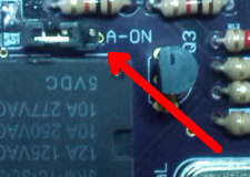
One important step if you're going to re-program the microcontroller on the veeOP is to use a jumper on the "A-ON header" (short for "always on"). Because the veeOP controls power to the Raspberry Pi, when programming it -- you don't want the veeOP to turn off your Raspberry Pi. When a jumper is on this header, it makes it so that the Raspberry Pi is always in an on state. It's also imperative that you take the jumper off when you're ready to put the veeOP back in your vehicle, as it won't function the way it's intended! ...As you might imagine.
Another option for programming the on-board arduino compatible microcontroller is to use the FTDI header on the board. This allows you to use an FTDI cable (which is basically a USB-to-RS232 adapter) to reprogram the microcontroller. Allowing you to program the micro without using the Raspberry Pi. However, since this also supplies the board with power, it's important that you do not have a micro USB cable attached, too.
Your veeOP should come with jumpers provided. However, if you are to lose them, any standard jumper from a PC will also work. (Or you can wrap a wire around them, in a pinch.)
Installing the necessary tools
If you're not using a veeOP customized distro, you might wish to install the tools from scratch. The examples given here are from Raspbian, but, can be easily applied to most distros.
First install Arduino and the requirements for inotools
sudo apt-get install arduino
sudo apt-get install python-setuptools
sudo apt-get install picocom
Then install ino with easy_setup
sudo easy_install ino
Add the pi user to the tty group
sudo usermod -a -G tty pi
And make a symlink to the tty that inotool / arduino likes...
sudo ln -s /dev/ttyAMA0 /dev/ttyACM0
And make sure it's writable
sudo chmod o+w /dev/ttyAMA0
Download the code!
- Main Article: Downloads
If you're using one of the downloadable pre-customized distros, you can look in:
/home/pi/arduino-vop/src/
For the source code. But, if you really want to dig in -- download the code from google code.
It's as simple as placing the vOP folder into your libraries folder in your Arduino's default install directory, to compile it. Check out the provided example sketch as it will guide you into extending the functionality. You can use the provided example sketch to keep the veeOP functionality intact, but! Use the microcontroller for other purposes, and it's extend it's functionality.
Using Arduino Shields with your veeOP
The veeOP is designed to be able to extend it using Arduino Shields. There are shields for all kinds of applications
- GPSr (global position system recievers)
- GSM (cell phone service)
- LCD Displays
- Wireless (like the ZigBee / XBee)
- And much, much more.
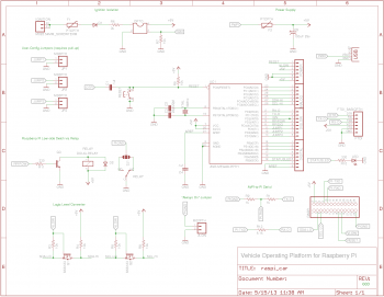
The Schematics
An extensible platform isn't exactly that without knowing how to really dig deep into the electronics. You can simply use the board "like an attached Arduino-compatible" -- or you can really get in and hack it how you want.
Or! You can even build your own. We've included the schematic to show you that we really do care about the Open Source Hardware (OSHW) movement.
Are you new to Arduino?
Don't sweat it! The Arduino is intended to be an approachable technology, and one that gives a new user a lot of power. And, you'll feel great interacting directly with microcontrollers. The best part is, you can use your veeOP to help you learn.
You can log onto the veeOP connected to your raspberry pi, but, you might want to download the Arduino IDE (integrated development environment) and get started on your workstation (your laptop or desktop computer). You can compile the veeOP code right there to do some initial testing and exploration.
Some resources you might be interested in:
- Getting Started With Arduino
- Arduino Software Download
- O'Reilly Arduino Development Landing Page
- The Arduino Cookbook
The I²C API
- Main Article: I²C API
The I²C API on the microcontroller is a rather simple little set of commands that rides on I²C. For more information about I²C we direct you to Wikipedia.
In practice, this is also abstracted by the veeOP REST API, which resides on the Raspberry Pi. The REST API is much more verbose, and provides more flexibility in handling the day-to-day tasks with your veeOP. But, should you see an opportunity to extend it's communication -- it's a simple system. Don't let all the bits and bytes confuse you here, when it comes down to it it's this simple:
- Raspberry Pi says "Hi, microcontroller, I want you to do something."
- ...And sends it 4 bytes to tell it to do so.
- Microcontroller says "Sure! I did what you want, and here's some info about it."
- ...And it sends 4-bytes back to the Raspberry Pi.
The veeOP uses the Raspberry Pi as the I²C master, with the arduino-compatible being the slave, at address 4 (0x04) by default (this is configurable in the library.)
Advanced Resources
Other resources that were valuable as the interface between the veeOP board and Raspberry Pi for programming the onboard arduino-compatible:
- Triggering microcontroller reset using Raspberry Pi's GPIO
- Another approach to programming an arduino compatible using a Raspberry Pi
- Fixing the DTR Pin
- Logic Level example schematics from eLinux
- eLinux's Serial Connection article
- An article about connecting serial communications to the Arduino from the Raspberry Pi


