Difference between revisions of "I²C API"
(Created page with " The I²C API on the microcontroller is a rather simple little set of commands that rides on I²C. For more information about [http://en.wikipedia.org/wiki/I%C2%B2C I²C we di...") |
Latest revision as of 13:23, 11 October 2013
The I²C API on the microcontroller is a rather simple little set of commands that rides on I²C. For more information about I²C we direct you to Wikipedia.
In practice, this is also abstracted by the veeOP REST API, which resides on the Raspberry Pi. The REST API is much more verbose, and provides more flexibility in handling the day-to-day tasks with your veeOP. But, should you see an opportunity to extend it's communication -- it's a simple system. Don't let all the bits and bytes confuse you here, when it comes down to it it's this simple:
- Raspberry Pi says "Hi, microcontroller, I want you to do something."
- ...And sends it 4 bytes to tell it to do so.
- Microcontroller says "Sure! I did what you want, and here's some info about it."
- ...And it sends 4-bytes back to the Raspberry Pi.
The veeOP uses the Raspberry Pi as the I²C master, with the arduino-compatible being the slave, at address 4 (0x04) by default (this is configurable in the library.)
Contents |
Download the code!
If you're using one of the downloadable pre-customized distros, you can look in:
/home/pi/arduino-vop/src/
For the source code. But, if you really want to dig in -- download the code from google code.
It's as simple as placing the vOP folder into your libraries folder in your Arduino's default install directory, to compile it. Check out the provided example sketch as it will guide you into extending the functionality. You can use the provided example sketch to keep the veeOP functionality intact, but! Use the microcontroller for other purposes, and it's extend it's functionality.
How Commands are transmitted
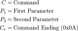
Commands are sent to the veeOP arduino-compatible with a 4-byte tuple. It looks like so:

Where each element is a single byte, representing:
-
 (command) is any (known) value other than 10 (0x0A, in hex.) and originally assigned all higher 10.
-
 &
&  are sometimes treated as individual integer values each, or together as a 16 bit integer, depending on context.
-
 Command ending allows the microcontroller know when a command is incomplete, or too many bytes are sent.
Why's it end in 10? It's the "end of line" ASCII character, check it out asciitable.com.
How responses are received
When the microcontroller recieves the proper 4 bytes for the command, it responds in turn with a response of 4 bytes.
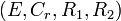
Where each element is a single byte, representing:
-
 errors of a value of 0 denotes an error-free response, any non-zero value is defined in a table below.
-
 is a redundant byte that represents from the sent command. This is used for error handling on the raspberry pi.
-
 &
&  are the resulting responses from the command. Treated as two bytes, or a 16-bit unsigned integer depending on the context of the command.
Commands
In this chart, we show each available command, and it's return type. The example commands and responses are given showing each 4-byte command and response, in decimal.
| Command Description | Value | |
|
Returns | Example Command (Decimal) | Example Response (decimal) | Example Description |
|---|---|---|---|---|---|---|---|
| Check Ignition State | 11 | - | - | Boolean | 
|

|
Response showing the ignition is on. An value of 1 denotes the ignition is on, where a value of 0 denotes it being off.
|
| Last time ignition changed (seconds ago) | 12 | - | - | 16-bit Integer | 
|

|
Responds showing us the ignition last changed it's state 258 seconds ago. See 16-bit integer note, below. |
| Last time ignition changed (minutes ago) | 13 | - | - | 16-bit Integer | 
|

|
Responds showing us the ignition last changed it's state 90 minutes ago |
| Pat the watchdog | 15 | - | - | - | 
|

|
Responds simply stating it pat the watchdog without an error. |
| Echo bytes sent | 14 | Byte | Byte | 2 Bytes | 
|

|
Simply echos the sent bytes back. Returns as and returns as . Mainly useful as
|
16-bit Integer Example
Using the "Last time ignition changed (seconds ago)" command example from above.
Note that and represent a 16 bit integer.In the response  could be represented as bytes in hex as
  , which will convert as a little endian into a decimal value of
Error Codes
| value |
Code Constant | Description |
|---|---|---|
| 1 | ERR_BUFFER_OVERFLOW | Too many bytes received before
|
| 2 | ERR_COMMAND_UNKNOWN | Command is unknown. |
| 3 | ERR_COMMAND_INCOMPLETE | Request for data from master received before sent.
|